Friday, 31 October 2014

Zabrano YaG-6 - Chassis


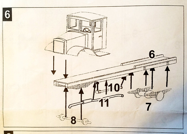
The irony is that the Zebrano YaG-6 kit isn't actually all that complicated - as you can see from the example of the assembly instructions that I have included above. And yet I feel mired in a succession of annoying little extra jobs just to get the kit to conform to the basic instructions.

One of the minor irritations related to a short-run resin kit like this seems to be how the manufacturer chooses to cast his parts. Obviously this is a complex process and they are dealing with delicate components, so the kit makers tend to attache parts to sections of resin - the resin equivalent of plastic sprues - to protect them and to help in the casting process.

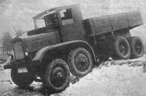
Actually only tenuously related to this project, but interesting. This rather blurry
photo shows a YaG-12. An experimental 1932 era 4-axle vehicle. The YaG's
unique independent suspension was copied from an ingenious British design.
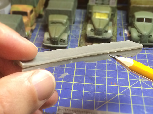
The YaG's chassis is a case in point. The whole length of the frame is attached to a long flat slab of resin which you will have to cut it from.


As you can see there is some nice detail on the chassis component - with the bottom of the engine block and front suspension moulded in between the front of the chassis frame.


But as you can see in the accompanying photo the supporting resin slab is quite thick and fairly well attached to the frame, which means some careful but determined sawing or cutting to separate the two.

Having done that it's time to check all the various components that make up the chassis assembly...
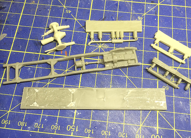
Note the large slab of resin at the bottom of the photo - this was the supporting
resin 'sprue' for the chassis frame!
Now here's one of those minor irksome issues that seems to characterise the Zebrano kit. Checking the parts off against the assembly sheet I notice that two of the parts don't look anything like they appear in the instructions!

By means of deduction I managed to identify the front axel and the drive shaft. But Zebrano's drawing still leaves you scratching your head about the precise placement of parts. You can just about make out where the rear suspension is supposed to rest on the chassis frame, but the exhaust pipe will have you trawling the internet for any YaG-6 photos so you can work out where it goes.

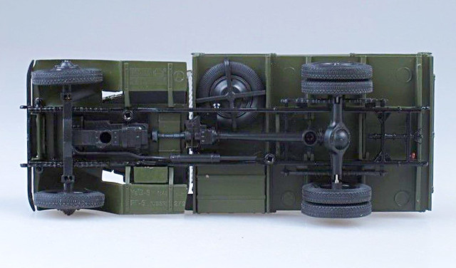
Unfortunately the best picture of the underside of a YaG-6 that I could find was a dodgy shot of the underneath of another YaG model...


Still, this is quite useful as it shows that the exhaust pipe runs on the right side of the engine and down the inside of the chassis frame. It also shows the position of the spare wheel - which will be useful even though the Zebrano spare wheel is missing from my kit! [Also note where the front wheels lay in relation to those huge mud guards.]

In the end I had to build up the rear suspension and add better supporting posts
to attach it to the chassis. I also extended the rear axel to widen the wheel
base. I just put the exhaust where I felt it looked right.
Another niggle is the method of fixing the wheels to the axels. The wheels have provision for some sort of fixing pins which you would imagine would be at the end of the axels - but no, there aren't any. I ended up drilling some holes into the axels and making my own pins out of some plastic rods.


I couldn't resist dry-fitting the main parts together to get an idea of what the finished model would look like (and to check fit and dimensions). This did indeed highlight a problem - the rear wheels are supposed to come out to align with the edge of the flatbed, so I will have to make a longer axel.

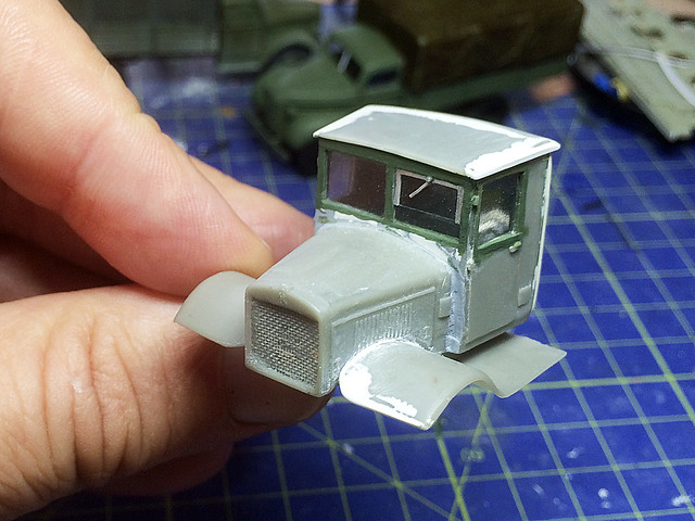
Note the front fender over-hang.
I should add that Zebrano haven't made it completely obvious where exactly parts are meant to joining with each other. A few 'pins' and holes would have been appreciated - as it is you just have to refer to photos and use your common sense when positioning the main parts.

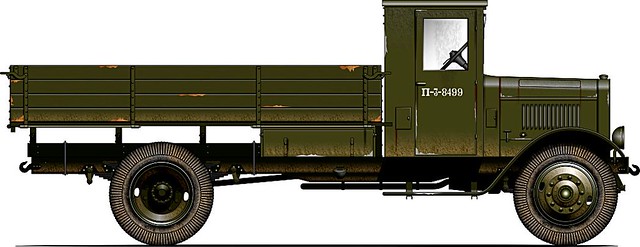
Left: Illustration reproduced with the kind permission of Oliver Missing of the 'Engines of the Red Army' web site. Source: © www.o5m6.de

Now, you might think that the same was true of the front axel and wheels, but actually these are in the right position and the huge fenders are supposed to over-hang to this degree. (But, yes, it does look strange.)

Well, it's getting there. There are a few things to sort out and some cleaning up and adding of little details. But the next post on this topic should be - fingers crossed - the base coating of the model.
Tuesday, 28 October 2014

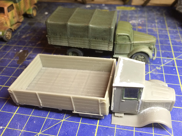
Zabrano YaG-6 - Cargo flatbed

This kit continues to be an aggrevation, there's not much pleasure in the construction process at all. Everything needs work and thus I am only making very small amounts of progress (which is a shame as I was so looking forward to making this model).

Despite thinking I had finished the construction of the cab I still ended up tinkering with aspects of the assembly that I just wasn't happy with.

Left: Illustration reproduced with the kind permission of Oliver Missing of the 'Engines of the Red Army' web site. Source: © www.o5m6.de (Note: These illustrations may not be re-published without permission.)

Aside from simply smoothing out lumps and bumps and filling gaps I also wanted to add a nice feature of the YaG-6's windshield - the driver's side split screen and window-wiper. So before I move on to the cargo flatbed I finished off the things about the cab that niggled me.


I'm not entirely convinced that Zabrano have captured the shape of the fenders correctly but I certainly did not want to go to the trouble of making completely new ones from scratch. So I settled for making both left and right mud-guards the same size as they didn't get that right either!


I finished off the planking on the rear cab - made with strips of metallic sticky-tape - and made a slightly better rear window, including some metal cross-bars. I don't think this is strictly authentic but I think it adds some nice decoration and looks right.

That done to my satisfaction it's time to move on to the cargo flatbed. Now according to the instructions this is the simplest of jobs, just gluing together the 5 components which are made up of the flatbed itself and the four walls of the cargo section.


...But guess what? It ain't that simple. All these parts need some sort of attention and are in one way or another the incorrect size. Additionally the fine details - such as the drop-side hinge-bars - are broken or completely missing in some cases.

Source: © www.o5m6.de

The cargo bed took some amount of sanding to get things to go together neatly, and I will have to make new hinge bars (easy enough). It just all more work.


Another aggravating thing is that the spare wheel - which is supposed to fit underneath the cargo bed - is missing! Because the YaG's wheels are a non-standard and larger size it's not something I can simply rectify by rummaging through my spares box. I may have to make a replacement, the hardest part of which will be replicating the distinctive tyre tread.

...Moan, moan, moan!

Anyway, let's try and end on some sort of positive note. Having made the cab and cargo bed I can now get some sort of idea about what size the finished model will be - and oh is it going to be a whopper!


I compared it to one of my medium trucks and it dwarfs my Ford V3000 by a good amount. A good job really as I intend this as one of my three heavy artillery towing vehicles (the real YaG-6 had a 5 tonne load capacity).

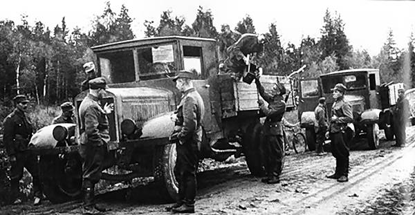
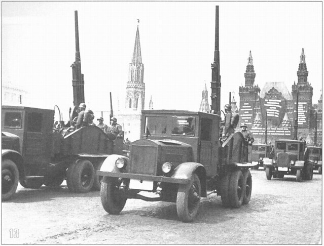
The model doesn't come with a tilt canvas cover but, actually, the two examples of this big truck that the Finns captured didn't have tilt covers fitted...

Source: SA Kuva archive
I guess I could make some cargo - ammo boxes, tarps and tools - to go in the cargo bed. But I haven't decided about that yet. It might be a bit bare if I don't put something in there.


Next: The chassis. (Any guesses how much work there will to be done on that?)

Sunday, 26 October 2014

Quick '39 Chevy Truck Part 6

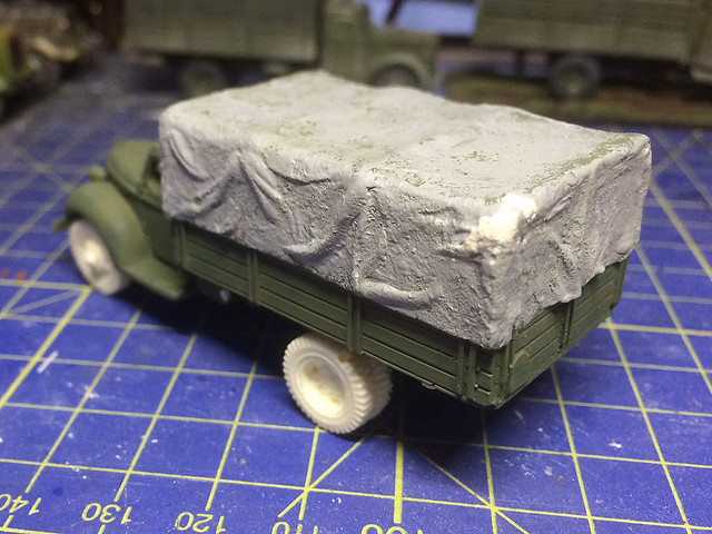
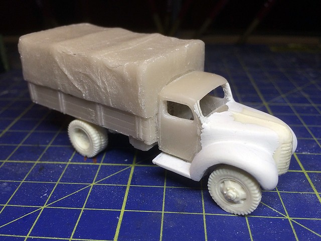
I began the base paint coat but soon found I wasn't happy with the tilt canvas. In order to make this truck look a little different from the other versions of the Valiant model I have I decided I needed to modify the canvas folds, just to make each version look a little more individual.

Using Milliput putty to add extra folds was easy enough, but then I found I needed to blend the additional detail in by using Mr. Surfacer with a stippling texture.


Once dry I gave the tilt quick spray of the Humbrol Light Olive base colour and then slapped on a sepia wash...


So, all the upper body base colours are done now but I have to install the driver and finish off the underside details. This means I might have to put in the windows now while I can still access the cab interior through the hole I made in the bottom of the cab.

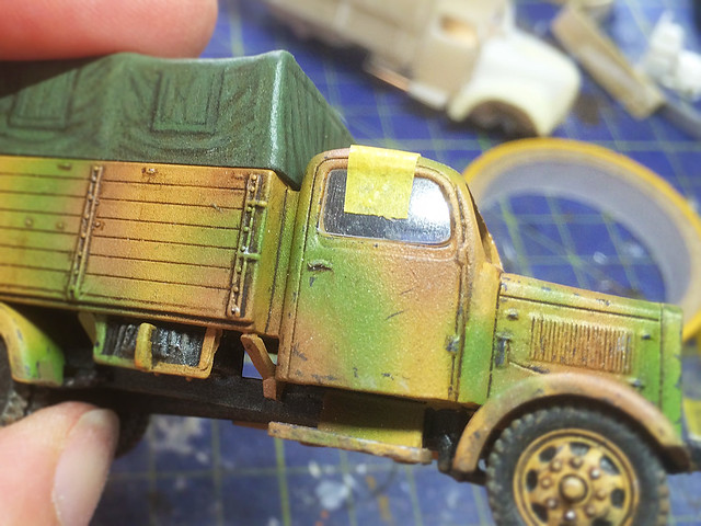
- I'm undecided which stage in the modelling is best to install windows in my trucks. I've tried leaving fitting the windshields until last, but on my YaG-6 model I fitted the windows quite early, but this time I'm putting them in during this mid-way stage. To be honest I think it might be different each time depending on the model. -
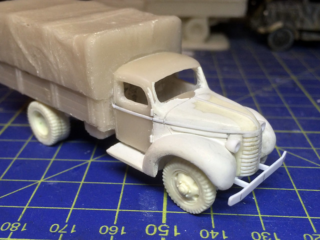
Anyway, once the windows are done I'll mask them out (just to be safe) and then start the pin-washing stage.

Wednesday, 22 October 2014

On the workbench, October 2014

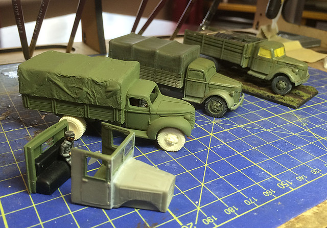
Just thought it would be nice to take a snap of the current workbench. At the moment I have a small fleet of Finnish trucks in various states of completion...


I found it amusing to see what is practically all the stages in my kit making process in the one place. From construction (YaG-6), to base coating (Chevy 1939), to highlighting (Ford Werkes V3000) to the final mounting prior to completion (Ford V3000).

Monday, 20 October 2014

Lancer Miniatures 1/72 T-20 Armoured Tractor

Feeding my minor obsession with getting the 'perfect' Komsomolet armoured tractor I took the advice of Greebs (a reader of this blog) and bought a Lancer Miniatures T-20. It wasn't a big outlay - especially compared to the North Star T-20 kit I featured in my last post on the subject - so I was easily able to sneak it under the wife's spending radar!

It arrived very promptly and here are some snaps of it...


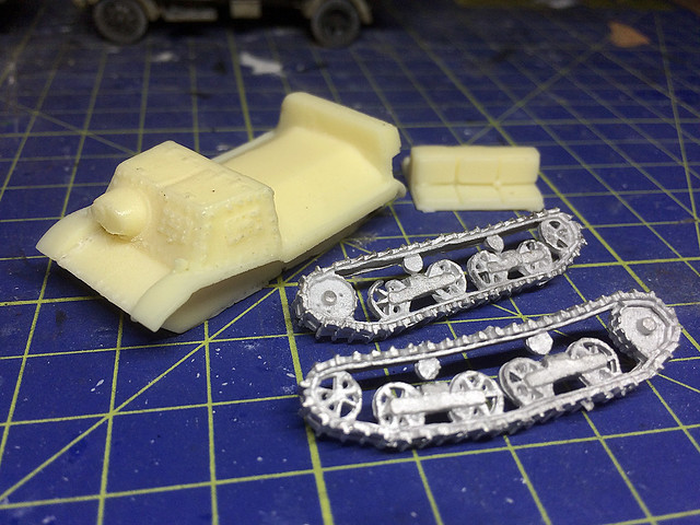
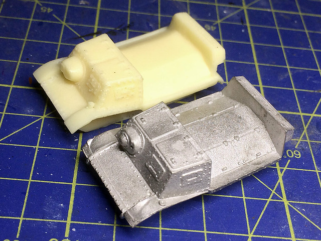
The Lancer resin T-20 hull compared to the white metal MMS T-20.
Excuse the muddy looking photos - but generally I was quite pleased with the product when you consider it was just £5.50. It is certainly better quality that the Shellhole Scenics T-20 (review here) and is about on par with the SHQ version of this little vehicle (review here). In the accompanying photo I have placed the resin Lancer T-20 hull component next to that of the MMS T-20 hull for comparison.

The Lancer is a gnat's hair larger than the MMS - which is understandable as the Lancer T-20 is supposed to be true 1/72 scale while the MMS is 1/76 scale - but as you can see the difference is barely discernible. As far as I can tell the Lancer's dimensions are just a tiny bit small for this scale which is why it seems compatible with the 20mm MMS model, but with such a small vehicle we are talking about fractions of millimetres differences here.

I know I keep including this reference photo, but this picture really does give an
excellent sense of just how small this 50hp armoured tractor was.
I am now of a mind that - really - any differences in scale from 1/76 to 1/72 are going to be negligible so I am going to clean up and paint both the Lancer and the MMS T-20s to see what they look like next to one of my finished trucks and some infantry figures. I only need three of these vehicles for my Finnish collection anyway so if they look OK I will probably complete the unit by making up the SHQ model.

T-20 Dimension comparisons:
1/1 Scale: Length: 3.45m | Width: 1.86m | Height: 1.58m
1/72 Scale: Length: 4.79cm | Width: 2.58cm | Height: 2.19cm
1/76 Scale: Length: 4.54cm | Width: 2.45cm | Height: 2.07cm


The general quality of the model is OK, there are a few bubbles on the resin component and the metal tracks have some gaps where the metal casting has failed. But for a Fiver I'm not moaning. I have to say that I had never heard of Lancer Miniatures before, so an additional thank you goes to Greebs for introducing me to a new source of interesting WW2 vehicle models.

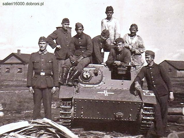
Another photo which gives you an idea of how small these vehicles were in
reality. These Germans stand beside a captured Soviet T-20, this will allow
me to make a good comparison with some 1/72 scale figures.
(Picture credit: Adam Salieri - salieri16000.dobroni.pl)

Link to the Lancer Miniatures website.

Sunday, 19 October 2014

Plastic Soldier Company 1/72 German Stowage set

All good things comes to he who waits! PSC have answered my wishes that someone makes a vehicle stowage set - not just with the usual crates, tarps and spare road-wheels but one that provides driver figures and other small items useful for 'dressing up' you vehicle model.
Click on picture to enlarge.
This set - which includes 3 of the above pictured sprues for £12.95 - also includes tank commander and driver figures, which is very welcome (given my moans about the lack of 1/72 driver figure sets).

There is enough in this set to embellish a large number of your German vehicles and it should last you quite some time so represents good value for money really. It's usefulness is not restricted to vehicle customisation either as the small items of personal infantry kit are particularly nice for undertaking figure conversions.

- Though a word of warning: PSC figures are slightly larger than most other makes of 1/72 figures - like Revell and ESCI, etc, so you may find the weapons a little large for integrating with other makes. -

This is a really nice set, although I still think it's missing some items, like spare headlamps and tools. Headlamps are so often neglected from 'quick build' models, as are horns, tow hooks and other smaller surface detail. But maybe I am being picky.

I hope PSC follow this set up with similar sets for other nations (Soviet set please). :)

Plastic Soldier Company - 1/72nd German stowage and tank commanders.

Saturday, 18 October 2014

Quick '39 Chevy Truck Part 5

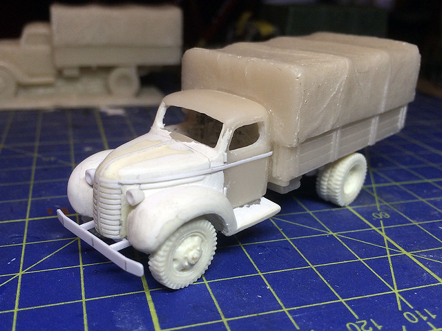
Completed the major work on this model with the final shaping and detailing of the bonnet, grill and fender assemblies. There turned out to be a lot more sanding to do than I imagined!


I'm really pleased with the final shape of the fenders, I managed to get the big rounded mud-guards looking about spot on (in my humble opinion, though they are a little too large). I guess you could say that all this work is a bit over-the-top when you consider that the overall cab shape is wrong for the '39 Cheverolet truck (being based on my Valiant Ford V3000 truck), but it looks passably like a Chevy!

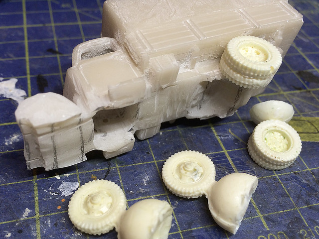
Having got the truck cab sorted it was time to work out how to attach the new resin wheels that my brother had sent me to the chassis...


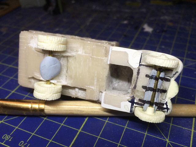
It's a bit of a fudge but I made a pair of axels out of some spare brass rods and attached them to the underside of the truck with some BlueTac so I could work out how to fit them correctly into position. I trimmed and sanded off the resin of the original chassis to make some rudimentary slots into which the axels could fit. I kept checking how the wheels fitted in relation to the flatbed and the fenders to ensure they were both centred properly and sat at the right height and were level.


Eventually it all came good(ish). The wheels look like they are in the right place and are secure, but I will put off fitting them permanently until I have finished off the cab detailing and have the cab interior installed.

The detailing includes all the fine panel lines around the engine hood and cleaning up the grill. Obviously I will be simplifying the detail, just adding a few bits and pieces to get the mock Chevrolet look I'm after.


So, there we go - a mock Chevrolet Model 1939 truck, of sorts. The main problem is that it's a bit too big, the original Chevy was a 1.5 ton truck based on Chevrolet's 1 ton pick-up truck cab - while my conversion is based on the 2 ton Ford V3000 which was a proper medium truck.

But, hey ho. It'll do in the absence of a proper 1/72 scale model of this vehicle (Minarions are working on a 1/72 scale Model 1937 Chevrolet which should be available in April of next year).

Next: Painting.

Thursday, 16 October 2014

1/72 T-20 Komsomolets Soviet armored tractor


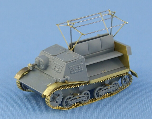
Quite a while ago I mentioned that the Latvian company North Star was working on a prototype for a true 1/72 model of the T-20 Komsomolets Soviet armoured tractor. This little vehicle - akin to the British Bren Carrier - was quite prevalent as a light AT gun tow in the Red Army at the beginning of WW2, but most importantly considerable numbers of them were captured by the Finn's during the ill-fated Russian incursion during The Winter War (1939-40).

Well, wonderful news. North Star have now released this model and it's an absolute beauty!

Picture source: North Star models
Picture Source: North Star models
For saying that it's such a small and somewhat insignificant vehicle (in terms of it's importance and role in WW2) North Star have poured a hell of a lot of superbly and very finely modelled detail into this tiny kit. It is a mix of resin components with photo-etched fine detailed parts and is firmly aimed at the display modeller and collector - this is in no way a war gaming quality model (if you seek that I'm afraid you will still have to make do with the 20mm incarnations made by MMS, SHQ or Shellhole Scenics).

Naturally I am particularly keen to get my hands on a true 1/72 model, principally because the vehicle is so small anyway that using a 20mm (1/76) model next to my other 1/72 vehicles would make it look all the more insubstantial and a bit silly. And because it was a vehicle that is so synonymous with the Finnish Army in WW2 I am going to have to bite the bullet and pay the premium asking price of $42 for one!

It will be very interesting to compare the 1/72 North Star T-20 with the very nice 20mm version made by MMS. Bearing in mind that I need three of these tiny vehicles if the size difference turns out to be negligible then I may stick with MSS for the remaining models I require.

(By the way, the North Star kit comes with decals for captured German examples!)

Full details are available on the North Star website: https://northstarmodels.com/

Link to my previous posts on the other makes of model T-20s that are available:
- Keeping things in proportion - SHQ 20mm T-20
- Shellhole Scenics 20mm T-20 review
- MMS T-20 Komsomolet in 20mm - white metal done right!

Sunday, 12 October 2014

Pegasus 1/72 German Army Truck - Part 8

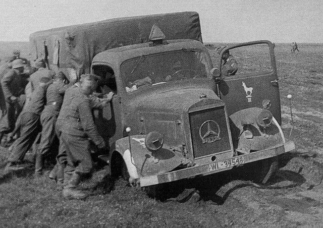
Mercedes L3000s stuck in the mud. Source: Autogallery.org.ru

Nearing the finishing line! (I always find this stage of making a model both exciting and rather disappointing. Sometimes I almost hate finishing a model because I have enjoyed the modelling process so much...Which is probably why I have a lot of unfinished models laying around my workbench!)


All that's left to do on my Pegasus German Army trucks is fit the 'windows'. And this is probably the fiddliest part.

As mentioned in my introduction to this project, the Pegasus 'quick build' trucks do not come with any transparent plastic parts for windows or headlamps. As these models are predominantly designed for use by war-gamers the notion is that widows are rather superfluous (or that the war gamer may opt to fill in the cab as a solid component and paint on faux windscreens).

I, however, am trying to make these pieces look more like display models so am adding some home made windscreens. The process is simple really - cut out some spare transparent plastic and glue the pieces into place. But for what it's worth here is my procedure for doing this...

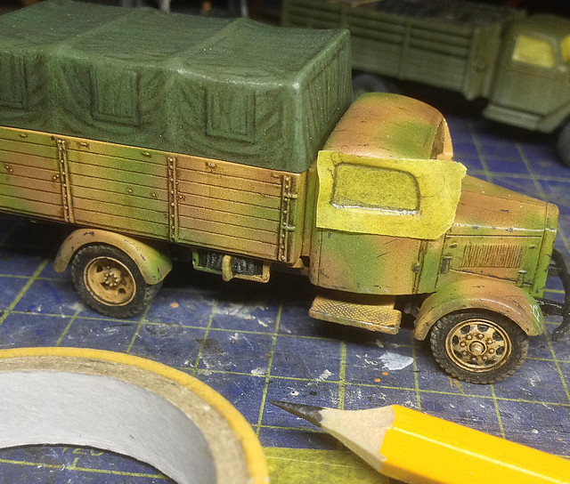
1. Draw window template.


I do this with a good point of a pencil onto a piece of masking tape so I get as close to the edges of the window-frame as possible. You can see how the pencil has pushed in the tape so I actually get an impression of the inside of the frame.

2. Transfer outline to transparent plastic.


I trace the shape of the window frame onto the transparent plastic. When I began modelling I bought sheets of transparent modelling plastic, that was before I realised that just as good quality plastic can be found on the blister-packs of much of our shopping!

3. Fitting the window panes.


The first window pane you do will need a bit of sanding to fit exactly. But once you have done this simply use this window as the template for your second side-window. By the way, the masking tape tabs are just to stop the windows falling into the cab (which is annoying), they also help hold the windows in place once they are glued.

For glue I use a PVA derivative called Formula '560' Canopy Glue by Pacer. I'm still not entirely convinced that this is any better than good old fashioned PVA, but the claim is that it dries 'crystal clear'. But I have found this is down to how much you use - the more there is the less likely it is to dry perfectly clear.

Lastly, I am considering doing some windscreen wipers and so might want to paint on some muck and dust so that you see where the wipers have wiped! What could possibly go wrong? :)

Next: Well, the next time you see these trucks they should be finished!

Thursday, 9 October 2014

Quick '39 Chevy Truck Part 4

Busy week - life get's in the way of hobbies! But I did manage to get a little bit done on my Chevy.


I made the resin Chevy bonnet for a PST 1/72 Ford 1943 truck kit which was a little narrower than the Valiant V3000 truck model. So I had to bulk out the new model with extra Milliput putty. This will need to be sanded smooth and then the details (like panel lines) added. But at least the bonnet fits now.
Next I made a very basic cab interior for the driver. Just a simple bench seat and floor...


Next: I'll work on the bonnet to make it a little more attractive than it is at the moment!

Monday, 6 October 2014

Quick '39 Chevy Truck Part 3

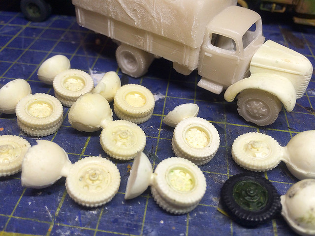
Oh! Look what the postman brought me. Lots of wheels!
Moving on...Or maybe moving sideways really. I've taken a diversion in this 'straight forward' project. Originally I had intended to keep the resin wheels that came with this 'ready to role' model, but it wasn't to be.

My brother has been busy with his resin experiments again and he sent me a lovely batch of truck wheels. I couldn't resist trying these out on my Chevy, so it was off with the old wheels and on with the new ones...


Had I been a little more careful I could have retained the original wheels, but inevitably I nicked them while I was using the Dremmel to cut away the excess resin attached to the underneath of the chassis. Adding these new resin wheels solves this problem which I would have had to otherwise repair using Milliput putty. It would have been do-able, but having the new wheels just seemed to be too good an opportunity to pass up.


I'm really pleased with my brother's wheels and they add to the effect I am trying to achieve - turning a solid one-piece model into one that looks a bit more like a multi-part kits so it blends in with the rest of my multi-part kits.

Next: Joining the Chevy bonnet component to the cab.

Sunday, 5 October 2014

Zabrano YaG-6 - Cab improvements

Just when you think you have done enough...You spot something else. I'm determined to make this kit as good as it can be because it cost so much. There's no good doing a half-assed job with it.

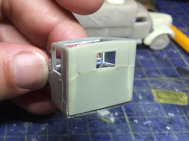
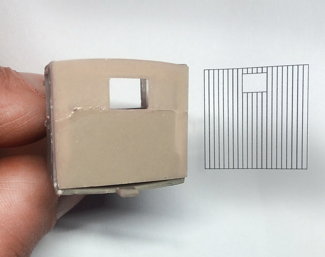
The Zebrano cab rear has no detail, and it's very thin. I broke
mine - you can see the crack - and I also noticed that the small
window isn't centred properly.
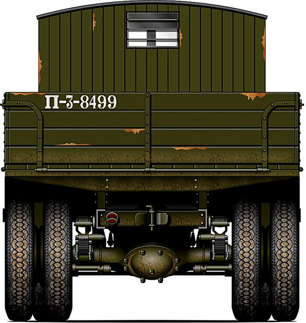
In this case I noticed that the rear of the Zebrano truck cab is very plain, but when I checked the available reference material the real thing has a distinctive wooden construction.

Illustration reproduced with the kind permission of Oliver Missing of the
'Engines of the Red Army' web site. Source: © www.o5m6.de
(Note: These illustrations may not be re-published without permission.)
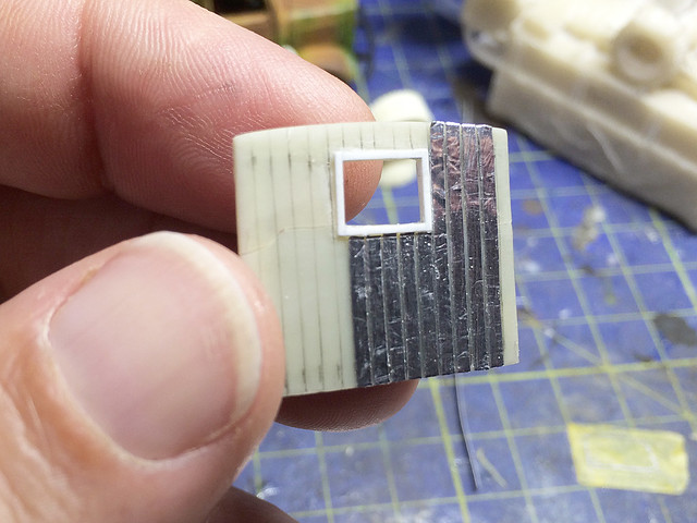
All these 'small jobs' add up - which is why I am having to do yet another post on the cab alone - but annoying as that is there is a simple fix for this one. I'm just using some more of that excellent metallic tape to apply strips onto the back of the cab to represent the planking of the original.
I drew a template for the wooden slats on my computer and
printed it out to scale, just to make sure I got everything
nice and even!
1.5mm strips of metallic tape represent the planked cab rear.
Metallic tape can be a wee bit tricky. I has a nasty habit of not sticking permanently and then lifts up again at some later date, so I'm experimenting with different liquid glues to stick it down securely. Also, after painting it the top coat can chip off revealing the shiny metal layer underneath.

I'm thinking I may have to use a good primer before adding the base coat.

Anyway, that's another little detour on the interesting journey that is Zebrano's YaG-6!

------------------------

End note: A big thank you goes to Oliver Missing of 'Engines of the Red Army' who has kindly allowed me to use his wonderful illustrations. His web site is undoubtedly one of the best sites for colour reference of WW2 Soviet war machines.

Next: Painting the interior.

Wednesday, 1 October 2014

Zabrano YaG-6 - Construction problems

The YaG 10 with AA gun. This shot - take in 1931 - give you a sense of just
how big the YaG trucks were.
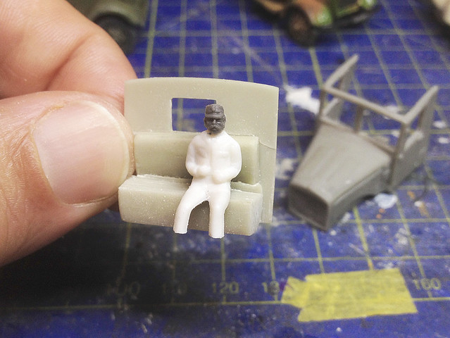
As hinted at in my earlier post I was already anticipating some construction problems (not a good start). The main issue was the warped resin cab, the walls were bowed and the whole thing wasn't square. On top of that the Zebrano kit does not come with a driver figure (don't get me started), so first things first, let's make a driver!

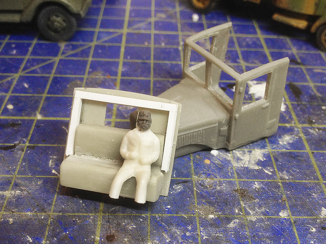
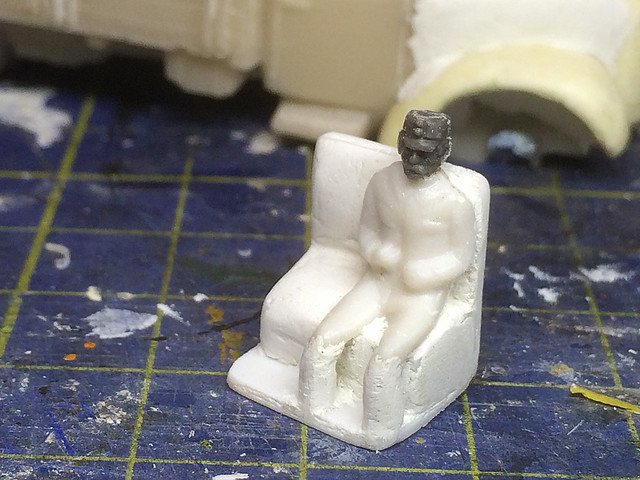
My brother sent me a load of HO (railway scale) seated civilian figures - I guess they are supposed to be passengers waiting at a station - and I have found these make useful driver bodies because of their slim size (they fit into compact vehicle cabs nicely). Onto one of these 20mm bodies I stuck a 1/72 HAT Austrian WW1 soldier's head.


Even though the body is quite 'svelt' I still had to amputate the feet to get it to sit at a pleasing height in the cab. I really like the Austrian's face, with his big bushy moustache! I had to cut down the crown of his field cap to make it more Finnish looking though.

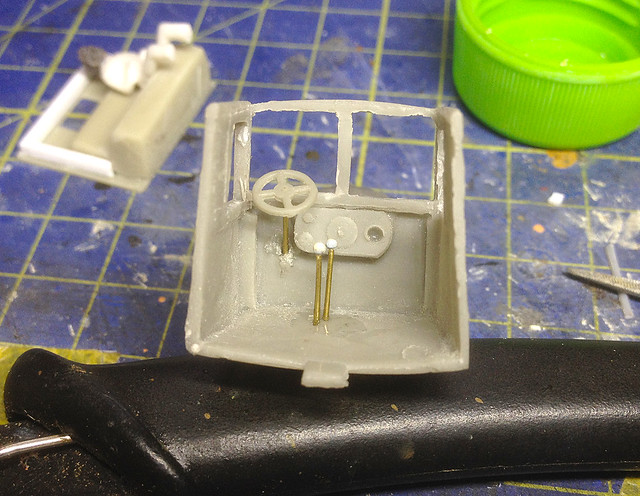
Now, having procured a driver I could now work out the placement of the steering wheel and gear levers (as the space is now very tight). I am placing the steering wheel just in front of the driver's lap, his hands aren't out-stretched to grab the wheel but I guess this will pass for a relaxed position (I'm not sure anyone will be able to see this fudge).

The Zebrano gear levers were a bit too short and feeble, so I made replacements.
This shot gives you a good idea just how warped the cab is!
Onto the tricky bit - straightening the cab walls.

The rear wall of the cab - with the integral bench seat - is a brittle component. I actually snapped off the top half (with the rear window) while trying to get this part to fit into the front cab component. When I did get it to fit in I discovered - another - two problems, the first being that the whole thing was askew and there were gaps and the second that the seat was - in my opinion - too high.

So, I sanded down the bench a bit until the driver sat at a comfortable height and then I began to make a rudimentary frame to help square up the bowed cab side-walls. (Though I do note - looking at reference photos - the driver does actually seem to sit very high in the cab.)


I believe (but please don't take me at my word though) you can re-form warped resin parts by submerging them in hot water and then gently pulling them back into shape. I think that as the resin cools again it hardens and retains it's new form.

Never having done this before though I decided to just let my frame take the strain! I was worried that the very brittle resin might snap if I tried mucking about with it.

Now, finally, it was time to dry fit al the parts into place...

Now I have the fenders fitted you begin to get an idea of the sheer size of this
beasty! I've put the YaG cab next to my Ford V3000 for scale.
Having done that I noticed that the front window frames were very wonky! So I decided to do a bit more sanding and bodging to get them square...

Added some styrene rods to straighten up the window frames. I can now
re-attach the fenders (which aren't matching either, what else can go wrong)!
Right! That's that. The cab is now complete - as per the instructions (but minus the clear windows) - and I am ready to mask off the windows and paint the interior and figure prior to permanently gluing the cab parts together.

Phew, what a kerfuffle.

Next: Painting the interior of the cab.